How Do You Test a Fuel Sending Unit in 7 Easy Steps
Are you tired of guessing whether your fuel gauge is accurate or not? Many car owners struggle with unreliable readings, which can leave you stranded or running low without warning.
Fortunately, testing your fuel sending unit is easier than you think, and you’re not alone in facing this issue.
To test your fuel sending unit in 7 easy steps, start by turning off your vehicle and disconnecting the battery negative terminal.
Locate the unit, then use a multimeter to measure resistance as you move the float arm to simulate different fuel levels—resistance should smoothly change.
Check the wiring and ground connections for continuity and damage.
Verify the gauge responds correctly when grounding the sender wire.
If you follow these steps, you’ll uncover potential faults and learn more about troubleshooting your fuel system.
Key Takeaways
- Access the fuel sending unit by locating and removing panels in the trunk or under the rear seat safely.
- Disconnect electrical connectors and drain fuel if necessary to prevent hazards.
- Use a multimeter to measure resistance across the sender terminals while moving the float arm.
- Check for smooth resistance variation as the fuel level changes. If the readings are inconsistent, it could indicate a fault.
- Inspect wiring and ground connections. Also, test the gauge response to see if it reacts correctly.
- These steps can help you identify wiring issues or problems with the sensor itself.
Prepare Your Vehicle and Gather Tools
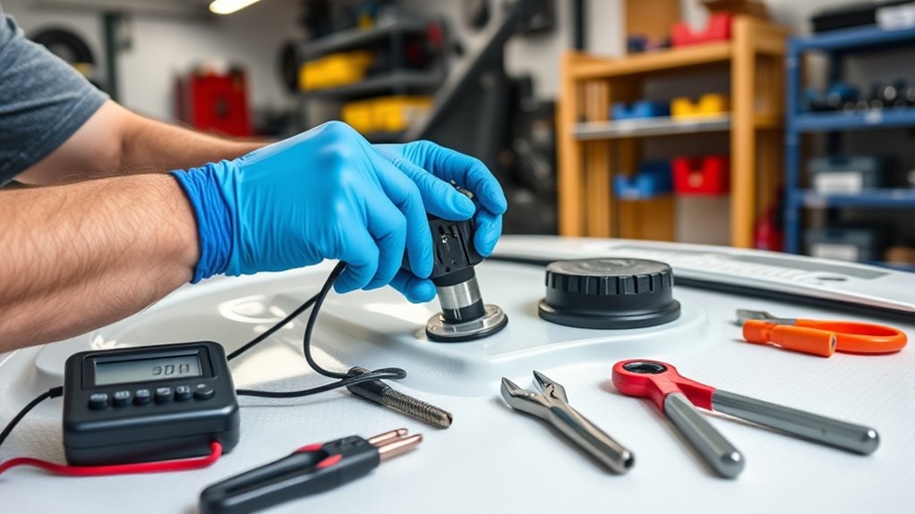
Before testing the fuel sending unit, make sure your vehicle is ready and you have the right tools. Turn off the engine and remove the key from the ignition for safety.
Gather essential tools like a multimeter, screwdrivers, and vehicle-specific wiring diagrams. These will help you do accurate testing and avoid mistakes.
Disconnect the negative terminal of the battery to prevent electrical shorts while you’re working. This step keeps you safe from sparks and electrical hazards.
Check your vehicle manual or repair guide to find the exact location of the fuel sending unit. Knowing where it is makes the process easier.
Having the right tools and safety measures in place makes the job smoother and safer. Always wear protective gloves and safety glasses when working around fuel and electrical parts.
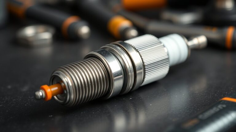
Locate and Access the Fuel Sending Unit
To locate the fuel sending unit, start by checking your vehicle’s service manual or wiring diagram to find its exact location. Once you know where it is, you’ll need to access it safely.
Look for an access panel or hatch, usually inside the trunk or under the rear seat. If needed, you might have to remove the fuel tank, which could involve draining or relieving pressure for safety.
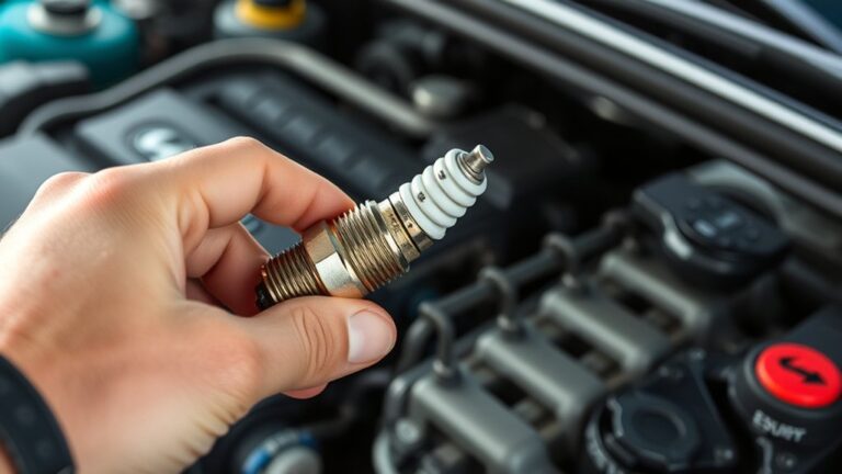
Use the right tools like screwdrivers, wrenches, or sockets to take off any panels, straps, or fittings holding the tank or access point. Be sure to disconnect electrical connectors carefully to avoid damage.
Accessing the fuel sending unit takes some preparation, but following these steps will help you reach it safely for testing or repairs.
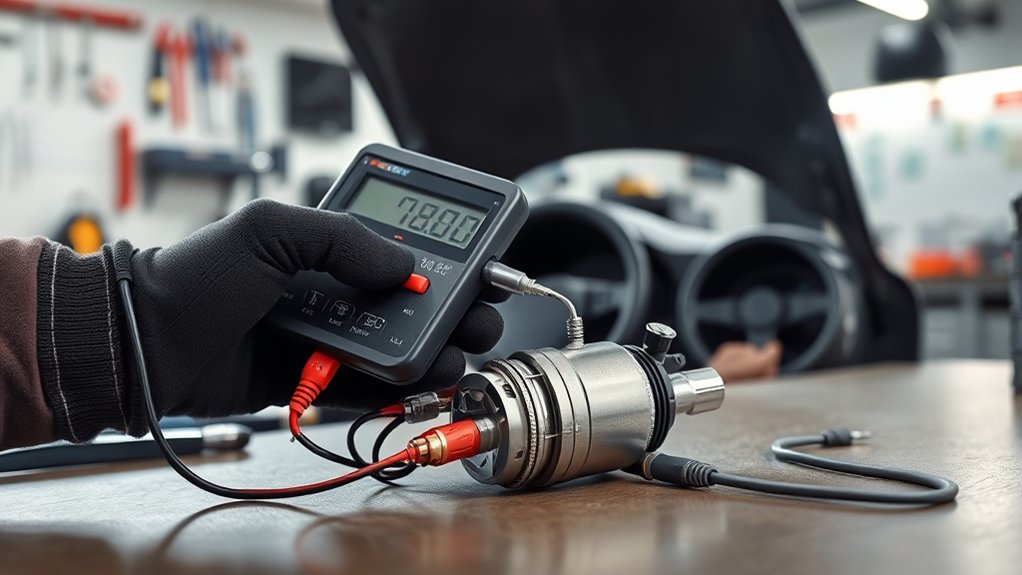
Measure Resistance of the Fuel Sending Unit
When measuring the resistance of the fuel sending unit, start by setting your multimeter to the ohms or resistance setting. Connect the multimeter leads to the sending unit’s terminals, making sure you have good contact for accurate readings.
As you move the float arm to different positions, watch how the resistance changes on the multimeter. Normally, a working sender shows resistance values from about 10 ohms when full to around 180 ohms when empty, depending on your vehicle.
If the resistance stays the same or falls outside these ranges, it signals a faulty sending unit that may need replacing. This resistance measurement helps you determine if the fuel sending unit is working properly or if it’s time for a new one.
Simulate Fuel Level Changes and Observe Resistance
Have you ever wondered how to check if your fuel sending unit works properly? You can do this by manually moving the float arm and watching the resistance with a multimeter.
As you raise or lower the float, the resistance should change smoothly. This shows the sender is responding to different fuel levels, just like it would in real conditions.
Raising or lowering the float should cause smooth resistance changes, indicating proper fuel sender response.
Move the float arm up and down to see how the resistance varies. Keep an eye out for consistent, smooth changes.
It’s a good idea to record the resistance at different positions so you can compare them later. Check if the resistance goes up or down depending on your sender’s design.
A proper response means your float arm and resistance mechanism are working fine. If the resistance is erratic or doesn’t change, there might be a fault in the fuel sending unit.
Check Wiring and Ground Connections for Continuity and Damage
Start by inspecting all wiring and connectors for visible damage, corrosion, or loose connections that could disrupt electrical flow.
Use a multimeter set to continuity mode to check for breaks or open circuits between the sending unit and the gauge.
Make sure the ground connection is solid by testing for continuity between the sending unit’s ground terminal and the vehicle’s chassis or negative battery terminal.
Inspect Wiring for Damage
Ever wonder if damaged wiring is causing your fuel gauge to malfunction? Inspecting wiring for damage is really important. Start with a visual check for corrosion, fraying, or burns along the entire length of the wire, especially where it connects.
Use a multimeter set to continuity mode to make sure there are no breaks between the fuel sending unit and the gauge. Look for signs like melted insulation or rust, which can mess with the signal.
Make sure ground connections are secure, free of rust or paint, and provide a solid electrical path. Wiggling or moving the wiring during testing can help reveal loose connections or intermittent faults.
Proper inspection ensures that wiring isn’t the hidden culprit behind your faulty fuel reading.
Verify Ground Connection Integrity
After inspecting the wiring for damage, the next step is to verify the integrity of the ground connection. Use a multimeter set to continuity mode to check for an unbroken electrical path between the ground wire of the sending unit and the vehicle’s chassis or negative battery terminal.
Inspect the wiring and connector terminals for corrosion, rust, or loose connections that could disrupt ground continuity. Confirm the ground connection is secure by tightening any loose bolts or terminals, making sure there’s metal-to-metal contact free of paint, debris, or rust.
Check for broken or frayed ground wires, as these can cause intermittent or complete loss of ground, affecting fuel gauge accuracy. Replace or repair damaged wiring or faulty grounding points to ensure a reliable connection and proper fuel sending unit operation.
Interpret Resistance Readings and Identify Faults
When testing your fuel sending unit, understanding the resistance range helps you figure out if it’s working right. Full tanks show low resistance, while empty tanks have higher values.
If the readings stay the same or change erratically as you move the float, that’s a sign of a possible problem.
Recognizing these patterns helps you quickly tell if the unit needs repair or replacement.
Resistance Range Expectations
Understanding the expected resistance range is essential for accurately testing a fuel sending unit. The resistance usually ranges from about 0 ohms when the tank is full to roughly 250 ohms when it’s empty, though this can vary depending on your vehicle.
If your resistance readings stay the same even as the float moves, the sender is probably faulty. An open circuit or infinite resistance usually means there’s a broken wire or a failed unit.
Values outside the specified range, like below 0 or above 250 ohms, suggest damage or malfunction. Proper operation is indicated by a smooth, steady change in resistance as the float moves.
Knowing these resistance expectations helps you interpret your readings correctly and figure out if your fuel gauge is showing the right fuel level.
Detecting Faulty Units
Detecting a faulty fuel sending unit involves analyzing your resistance readings as you move the float arm. If the resistance stays the same, it could mean there’s a problem like a broken resistor or corrosion.
Resistance readings outside the manufacturer’s range suggest an open circuit or short, pointing to a defective unit. Look for signs of damage such as corrosion, broken wires, or a stuck float arm, which can cause inaccurate readings.
To test the fuel gauge, check that the resistance varies gradually with the fuel level. Use the table below to interpret your readings:
| Resistance Behavior | Possible Issue | Action |
|---|---|---|
| No change with float movement | Faulty or broken resistor | Replace the sending unit |
| Constant high or low reading | Open circuit or short | Inspect and repair wiring |
| Resistance outside range | Damaged or malfunctioning unit | Replace the sensor |
| Gradual variation | Healthy unit | Good to go! |
Recognizing Inconsistent Readings
Inconsistent resistance readings during testing often point to issues within the fuel sending unit or its wiring. Sudden jumps, no change despite moving the float, or fluctuating resistance can indicate internal damage or corrosion in the sensor.
If resistance stays the same when adjusting the float, it suggests a broken or stuck wiper arm or internal resistor. Fluctuating resistance readings that don’t match fuel level changes often come from damaged wiring, loose connections, or electrical faults.
To identify faults, compare your readings against manufacturer specifications. Look for signs like sudden resistance jumps or no change when moving the float, resistance values that don’t vary smoothly with float position, resistance remaining constant despite float movement, or fluctuating readings that don’t match fuel levels.
Recognizing these inconsistent resistance patterns helps pinpoint wiring issues or faulty sending units.
Verify Fuel Gauge Response and Final Troubleshooting
To verify that your fuel gauge responds correctly, start by turning the ignition on and watching the needle as you fill or empty the tank. If it moves appropriately, your gauge might be fine.
To confirm, disconnect the sender wire and ground it. If the needle moves to full, the gauge is working properly. Use a multimeter to measure resistance across the sender’s terminals; resistance should change smoothly as the float moves.
Also, check the wiring connections—make sure they’re clean, intact, and free of corrosion. If the gauge doesn’t respond, verify the sender’s resistance and the wiring.
Here’s a quick overview:
| Step | What to Check | Expected Result |
|---|---|---|
| Turn ignition on | Observe gauge movement | Needle moves with tank level |
| Disconnect sender wire | Ground wire, check response | Needle moves to full |
| Measure resistance | Across sender terminals | Resistance varies smoothly |
| Check wiring | Connections and cleanliness | Properly connected, clean wiring |
Frequently Asked Questions
How to Test if a Fuel Sender Unit Is Working?
To test if your fuel sender unit is working, start by disconnecting it and measuring resistance with a multimeter as you move the float.
Make sure the unit has the proper voltage supply, usually around 5V or 12V.
Adjust the float and watch if the resistance changes smoothly within the specified range.
Manually move the float to see if resistance varies proportionally, which indicates the sender is functioning correctly.
If the readings don’t match the expected values, the unit might be faulty.
How to Test the Ohms on a Fuel Sending Unit?
To test the ohms on a fuel sending unit, set your multimeter to the ohms (Ω) setting. Disconnect the unit from your vehicle and connect the probes to its terminals.
Next, move the float arm or simulate different fuel levels, then watch how the resistance changes. Compare these readings to the specifications in your vehicle’s manual.
If the resistance changes smoothly and consistently, it indicates a good unit. But if the readings stay static or are out of range, that suggests a fault.
How Do I Know if My Fuel Pump Sending Unit Is Bad?
Did you know that over 60% of fuel gauge issues come from faulty sending units?
To see if yours is bad, look for inconsistent or stuck readings—like always showing full or empty.
If resistance readings don’t change when you move the float arm, or if the gauge reacts erratically even with good wiring, your sending unit’s probably failing.
Also, check for corrosion, damage, or worn parts on the float or arm—that can give you clues it’s time to replace it.
How Many Volts Should a Fuel Sending Unit Have?
A fuel sending unit should have around 5 to 12 volts, depending on your vehicle’s electrical system.
When you turn on the ignition, you should see a stable voltage close to your car’s standard system voltage, usually around 12V.
If the voltage is much lower or fluctuates, it could indicate wiring issues or a faulty power supply, which can affect the sender’s accuracy.
Conclusion
Now that you’ve followed these steps, testing your fuel sending unit is like solving a puzzle. You’ll identify issues and get your fuel gauge back on track.
Remember to stay patient and methodical. Each step gets you closer to the solution.
With a little practice, you’ll confidently diagnose and fix fuel sender problems, saving you time and money.
Keep at it, and soon your fuel gauge will be as accurate as a clock, guiding you smoothly on every drive.